
I’m a self‑driven, results‑focused professional with a broad skill set and a proven history of delivering meaningful impact. I don’t just provide solutions; I actively pursue them. When I don’t have an answer or direction, I research, test, and uncover it. My priority is helping organizations grow, perform, and succeed through competence, adaptability, and strategic execution.
Engineering, Technical Experience & Services
Phone: 661-365-5792
-
Product R&D and Product Management, Design for Manufacturing (DFM) across Consumer Electronics, Pro/Commercial environments for Audio‑Video, Security, Home Automation, LED Lighting, AC/DC Power, Wired/Wireless Networking, and IP/PoE systems. Experienced in taking hardware and software designs from proof‑of‑concept through full product launch.
-
Value‑Added Product Solutions Engineer with deep expertise in creating innovative, market‑ready solutions.
-
Electronic Engineering, Technical CAD drawings, and Consulting for product development, system architecture, and engineering documentation control/management.
-
Residential and Pro Audio/Commercial AV, Lighting, Security and Automation System Integration, including technical design, system layout, and implementation strategies for new construction projects and retrofits.
-
Creation and design of product catalogs, brochures, technical literature, instruction manuals with detailed product information/ technical specifications, packaging, website technical information/diagrams, and application notes.
-
UI/UX Design for intuitive, user‑focused interfaces across hardware and software platforms.
-
Development of technical training materials and support documentation for sales teams, trade shows, and partner education.
-
Creation of technical concepts, imagery, and presentations for customer engagement, email campaigns, LinkedIn content, training, and marketing initiatives.
-
Marketing support through technical resources, product insights, and strategic guidance to strengthen brand awareness and identify key markets and customer segments.
-
Extensive familiarity with industry leaders in AV and home automation products, systems, and technologies.
Please Note! This website is constantly in flux and a work in progress and is being updated, modified on a reqular basis.
CAD Technical Blueprints & Architectual Drawings, Drawing Takeofffs are Vital Documents to every successful project
Audio-video systems, networking infrastructure, and commercial-home automation solutions rely on precise coordination across multiple discipline and that’s where CAD technical blueprints and architectural drawings become indispensable. These documents serve as the visual and technical backbone of any successful project, translating complex engineering concepts into actionable layouts that guide technical professionals and engineers for overall design elements, installations, integration of multiple technologies, and the ability to provide details for long-term maintenance. They ensure that every cable run, device placement, signal path, and control interface is accounted for within the physical and structural constraints of the space. More importantly, they foster collaboration between AV designers, IT professionals, electricians, and architects for reducing errors, avoiding clashes, and streamlining workflows. Without these drawings, even the most advanced systems risk misalignment, inefficiency, and costly rework. In short, they’re not just plans, they’re the language of precision and project success from start to finish. Having detailed CAD drawings is essential to your team's success and reflects your dedication to precision, planning, and client trust.
I live by this process in all my work! Sometimes creating AV diagrams and important technical information takes extra time because every detail truly matters. A well‑built drawing and document system keeps project managers aligned, gives programmers a clear blueprint, and makes the installation smoother for the technicians in the field. The objective is always the same: fewer surprises onsite, stronger communication across teams, and a clean, professional final result everyone can be proud of. I apply this process to everything I do when engaged for myself and everyone in the team for a successful project outcome.
Explore
AV, Lighting, Security, HVAC , CCTV, Shades, Wired/Wireless Networking, Home Automation Technical Drawings, using ANSI/AVIXA Standards

All Drawing Designs can contain links to the following information:
-
Product Owners Manuals
-
Digital Media such as Product Images or Videos
-
Component Hardware & Wiring Technical Specifications
-
Project Notes!
-
Project Room Images
-
Control System Touchscreen Mockups
-
Links to ANSI/AVIXA standards for reference information
AV System Integration Schematic Diagrams

Interactive Bar Schematic Diagram with Audio-Video/ Networking/Control. Click Here to open the Interactive PDF document.
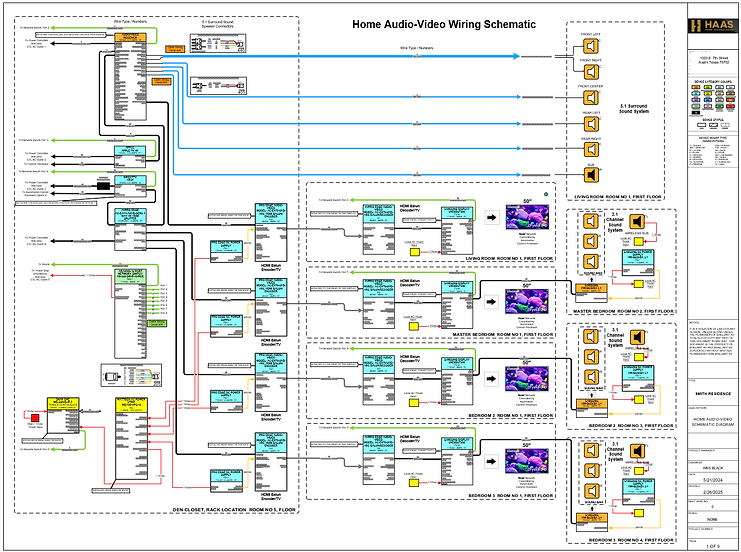
Home Audio Video, Network, Power management Schematic Diagram.
Click Here to open the PDF document.
EERO Pro Wi-FI 6 Signal Topology Reflected Ceiling Diagram

Rack Elevation Diagrams
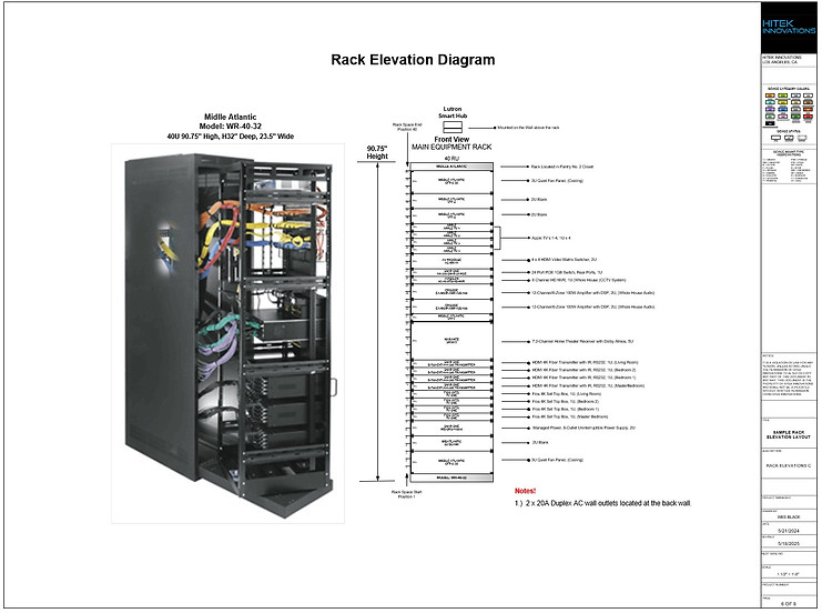
Audio Video, Power, Networking, Control System Sample Rack Elevation Diagram. The design process can also allow for both Front and Rear rack views.
Click Here to open the PDF document.
AV Block Diagrams

Block Diagram data can be imported from your project BOM files via excel spreadsheet format directly into the CAD design software. Block Diagrams can be created and shown in a basic format or with lots of details, information and specifications. The BOM can be shown with or without both Room details and Manufactures details in the drawing. View of Cad software tools and Installation Block Diagram by Rooms and Products. Click Here to open the PDF document.

Full page view of the Installation Block Diagram by Rooms and Products. Click Here to open the PDF document.
Sonance Multizone Audio Using Alexa Block Diagram Example

Alexa Echo Multi-Zone Block Diagram by Rooms and Products.
New Reference Interface Balun Design POC that was provided to Sonance.
Click Here to open the PDF document.
(SOW) Scope of Work Schematic Diagram Example

Engineering Staff: Technical Device Connectivity (SOW) Scope of Work Example Diagram for Audio-Video-Power-Control System.
Click Here to open the PDF document.
Project (SOW) Scope of Work Process and Details
Audio Video (AV) and Home Automation projects should have a blueprint, it outlines exactly what’s being delivered, how it’s being done, and who’s responsible for what. It ensures everyone’s on the same page from design to installation to final handoff to the client.
Details, Project Overview:
-
Description of the property (e.g., new construction, retrofit, size, number of physical rooms and information that outlines technologies for each area.
-
Client goals (e.g., whole-home audio & video, theater room, smart lighting, shades, CCTV cameras, alarm system, and other home automation specifics.
Systems to be Integrated, Local Control and Remote Access:
Audio/Video: Multi-room audio, surround sound, distributed video
Lighting & Shades: Smart Lighting Scenes, automated blinds
Climate Control: Thermostat Integration
Security & Surveillance: Door/Area Access, Cameras, motion sensors, door/window contacts
Networking: Wired/wireless infrastructure, WAP wireless access points
Control System: Centralized control via touch panels, remotes, mobile apps or voice control
Deliverables:
-
Equipment list (brands, models, quantities)
-
Wiring diagrams and schematics
-
Rack layout and labeling
-
Programming and user interface customization
-
Training and documentation for the client
Timeline & Deliverables:
Produce commissioning schedules aligned with system design and scope
-
Pre-wire phase
-
Trim-out and equipment installation
-
Programming and testing
-
Final walkthrough and sign-off
Quality & Testing Standards:
-
Functional testing of all systems
-
IP rating verification for outdoor gear
-
Thermal management and ventilation checks
-
Compliance with industry standards (e.g., AVIXA, CEDIA)
Responsibilities:
-
Who supplies what (client vs. integrator)
-
Coordination with other trades (electricians, HVAC, builders)
-
Warranty and support terms
M&E *Mechanical/Electrical) Drawings
Coordinate the Production, Revisions of M&E Drawings with other CAD engineers if required, also with Project Management Teams so everyone has the current changes and all staff is on the same page
M&E stands for Mechanical and Electrical. These drawings are technical schematics that detail the layout, specifications, and integration of mechanical systems (like electrical systems, lighting, power, AV, data hardware & cabling) within a building or space.
CAD Team refers to the group responsible for creating these drawings using Computer-Aided Design (CAD) software such as AutoCAD, D-Tools, Revit, Vizio, or Vectorworks or other industry standardized software.
What This Task Involves:
-
Collaborating with Engineers and Designers: Ensuring that all mechanical and electrical requirements are accurately captured and reflected in the drawings.
-
Providing Technical Input: Supplying specifications, equipment lists, and layout details—especially for AV systems, power requirements, and cable routing.
-
Reviewing and Approving Drafts: Checking for accuracy, compliance with standards, and coordination between disciplines (e.g., avoiding clashes between ductwork or plumbing and AV cabling).
-
Maintaining Version Control: Ensuring the latest revisions are distributed and implemented across all stakeholders.
-
Aligning with Project Timelines: Making sure drawings are produced on schedule to support procurement, installation, and commissioning phases.
In AV system design, this coordination is critical to ensure that your cabling, racks, displays/mounts, additional AV hardware, and control interfaces are properly integrated into the architectural and electrical plans.
Audio‑Video & IT Project Takeoffs
'The bridge between engineering design and project execution'
Audio‑Video (AV) and IT project takeoffs are the detailed process of identifying, quantifying, and documenting every device, material, cable type, pathway, and installation requirement needed to build a complete system. They translate design intent, shown in CAD drawings, schematics, block diagrams, and architectural plans into a precise bill of materials (BOM), labor scope, and cost structure.
AV/IT takeoffs are the technical and financial blueprint for executing a project correctly. They ensure that what’s drawn, specified, and promised is exactly what gets installed—no surprises, no gaps, no rework.
Typical Construction / Audio Video, IT-Automation, CCTV, Technology Hardware Blueprints are usually created and printed in these industry standard sizes
Primary Blueprint & AV Drawing Sizes (North America)
-
ARCH D (24" x 36"): The most common standard for full-size construction drawings, including architectural, structural, and electrical plans.
-
ARCH E1 (30" x 42"): Often used for larger projects or more detailed, dense, technical drawings.
-
ARCH C (18" x 24"): Common for smaller projects, individual detail sheets, or reduced sets.
-
ARCH E (36" x 48"): Used for large-format, comprehensive, or detailed sets.
-
ANSI D (22" x 34"): Another standard for full-size, allowing for easy reduction/scaling to 11" x 17".
Common Smaller/Reduced Sizes
-
ANSI B (11" x 17"): Frequently used for "half-size" sets, "red-line" revisions, or site, electrical, and AV plans that don't require huge paper.
-
ANSI A (8.5" x 11"): Reserved for specifications, transmittals, or single-detail
Why Takeoffs Matter in AV, IT, and Automation Projects
1. Accurate Material Quantities
Takeoffs ensure you know exactly what the project requires:
-
Displays, speakers, amplifiers, DSPs
-
Network switches, WAPs, PoE loads
-
Cable lengths by type (Cat6A, fiber, speaker wire, control wire)
-
Mounts, plates, connectors, racks, power distribution
This prevents under‑ordering, over‑ordering, and costly delays.
2. Clear, Organized Bill of Materials (BOM)
A takeoff converts drawings and schematics into a structured BOM that aligns with:
-
Room‑by‑room layouts
-
System block diagrams
-
Rack elevations
-
Wiring schematics
3. Labor Planning & Installation Sequencing
Takeoffs define:
-
Pre‑wire requirements
-
Trim‑out hardware
-
Final installation tasks
-
Programming and commissioning needs
4. Coordination With Other Trades
AV/IT takeoffs align your system with:
-
Electrical plans
-
Mechanical layouts
-
Architectural constraints
-
Low‑voltage pathways
-
Ceiling plans and reflected ceiling diagrams
5. Costing, Bidding, and Project Management
A proper takeoff is the foundation for:
-
Accurate bids
-
Competitive pricing
-
Change order control
-
Procurement scheduling
-
Project forecasting
What a Complete AV/IT Takeoff Includes

Touchscreen GUI Designs and Mockups
Touchscreen Mockup Menu demonstrates graphics for Controlling Lighting Zones on a Floor Plan Layout. Click Here to open the PDF document.


Push Play
Touchscreen Mockup with Interactive Demo Menu, this video demonstrates graphics for Controlling Lighting Zones on a Floor Plan Layout, control any zone or zones manually or select the All Lights On command which initiates a macro with a 2 second delay between each zone to prevent large current surges to the electrical system. Select the Play Button on the Touchscreen Image above to start the Video.
Equipping field sales teams with interactive design tools on a portable tablet transforms customer demos into immersive experiences that bring cutting-edge technology to life and empowering clients to envision exactly how these solutions can elevate their home or business.
By tailoring each demo to a customer’s unique needs, sales staff and programmers can collaboratively refine designs in real time—long before any hardware is installed or code is written. Even audio and video media can play in real time for further enhancement of the user experience.

VDC (Virtual Design and Construction): What It Is and Why It Matters
VDC (Virtual Design and Construction) is a project‑delivery methodology that uses digital models, data, and collaborative workflows to plan, design, coordinate, and build a project before physical construction begins. The core idea: simulate the entire project virtually so teams can detect issues, optimize performance, and reduce cost and risk in the field.
1. What VDC Includes
VDC isn’t just 3D modeling — it’s a coordinated framework built around three components:
-
BIM (Building Information Modeling) The 3D/4D/5D model containing geometry, materials, schedules, and cost data.
-
Integrated Project Delivery (IPD) Workflows Cross‑disciplinary collaboration between architects, engineers, contractors, and technology trades (AV, IT, security, MEP).
-
Project Metrics & Simulation Using digital tools to predict outcomes: cost, schedule, logistics, clashes, energy use, system performance, etc.
2. What VDC Does
VDC enables teams to:
-
Coordinate all trades digitally (MEP, AV/Automation, IT, security, structural, architectural)
-
Identify clashes before construction (e.g., conduit paths, rack locations, cable trays, speaker placements)
-
Optimize installation sequencing
-
Improve accuracy of drawings and submittals
-
Reduce rework, delays, and change orders
-
Provide owners with a complete digital twin for operations and maintenance
For AV/IT/security integrators like you, VDC is especially powerful because it ensures:
-
Correct pathways and rack locations
-
Accurate device elevations
-
Proper power and network provisioning
-
Clear coordination with electrical, mechanical, and architectural teams
-
Fewer field surprises and redesigns
3. How VDC Differs From BIM
A lot of people confuse the two. The distinction is simple:
-
BIM = the model
-
VDC = the process that uses the model to manage the project
BIM is a tool. VDC is the strategy.
4. Why VDC Is Becoming Standard
Owners and GCs increasingly require VDC because it delivers measurable benefits:
-
20–30% reduction in rework
-
Faster project delivery
-
Lower overall cost
-
Higher installation accuracy
-
Better lifecycle documentation
For technology systems (AV, automation, networking, CCTV), VDC ensures your designs are fully integrated into the building model, not treated as an afterthought.
5. A Clean, Site‑Ready Definition (Wix‑friendly)
Virtual Design and Construction (VDC) is a collaborative project‑delivery method that uses digital models and data to plan, coordinate, and simulate a building before construction begins. VDC integrates BIM, engineering workflows, and project analytics to reduce risk, eliminate clashes, improve accuracy, and streamline installation across all trades — including AV, IT, automation, and security systems.
CAD Systems Integration Engineering for Commercial & Consumer Technologies
*Audio/Video *Automation *HVAC *Lighting Interior/Exterior * Wired/Wireless Networking * CCTV/Security *Energy Management *Rack Elevations * Wall Elevations *Rough In Plans *Room Schematics * Shades * A/V Floor Plans *System Block Diagrams * Wiring Schematics * Wire Terminations
'Finding Inspiration in Every Turn, empowering design excellence'