
I’m a self‑driven, results‑focused professional with a broad skill set and a proven history of delivering meaningful impact. I don’t just provide solutions; I actively pursue them. When I don’t have an answer or direction, I research, test, and uncover it. My priority is helping organizations grow, perform, and succeed through competence, adaptability, and strategic execution.
Engineering, Technical Experience & Services
Phone: 661-365-5792
-
Product R&D and Product Management, Design for Manufacturing (DFM) across Consumer Electronics, Pro/Commercial environments for Audio‑Video, Security, Home Automation, LED Lighting, AC/DC Power, Wired/Wireless Networking, and IP/PoE systems. Experienced in taking hardware and software designs from proof‑of‑concept through full product launch.
-
Value‑Added Product Solutions Engineer with deep expertise in creating innovative, market‑ready solutions.
-
Electronic Engineering, Technical CAD drawings, and Consulting for product development, system architecture, and engineering documentation control/management.
-
Residential and Pro Audio/Commercial AV, Lighting, Security and Automation System Integration, including technical design, system layout, and implementation strategies for new construction projects and retrofits.
-
Creation and design of product catalogs, brochures, technical literature, instruction manuals with detailed product information/ technical specifications, packaging, website technical information/diagrams, and application notes.
-
UI/UX Design for intuitive, user‑focused interfaces across hardware and software platforms.
-
Development of technical training materials and support documentation for sales teams, trade shows, and partner education.
-
Creation of technical concepts, imagery, and presentations for customer engagement, email campaigns, LinkedIn content, training, and marketing initiatives.
-
Marketing support through technical resources, product insights, and strategic guidance to strengthen brand awareness and identify key markets and customer segments.
-
Extensive familiarity with industry leaders in AV and home automation products, systems, and technologies.
Please Note! This website is constantly in flux and a work in progress and is being updated, modified on a reqular basis.
Networking Wired/Wireless (Wi-Fi) Systems Info & Hardware
A hybrid network of wired and wireless infrastructure is the backbone of a reliable, flexible, and future-proof system for Audio, Video, Security, and Automation hardware. Each type plays a unique role and together, they create a well-connected eco system that’s both powerful and adaptable for Home and Commercial applications.
T


Wireless Tablets & Phones
Wi-Fi 7 Wireless Access Points
Hard Wired Managed PoE Switches
Wireless Lighting Controls
Hard Wired Automation Controller
Wireless Thermostats
Hard Wired PoE CCTV Camera's and NVR's

Hard Wired SDVoE Devices

Hard Wired Multizone Audio Systems

Wireless Door Locks

Video Conferencing Systems
Planning strategy for a Wired and Wireless Networking Eco system
1. Define Use Cases & Zones
-
Core AV Systems: Media rooms, distributed audio/video, home theater.
-
Automation Devices: Lighting, HVAC, shades, security, sensors.
-
User Interfaces: Touch panels, mobile apps, voice assistants.
Network Zones:
-
Backbone: High throughput wired infrastructure.
-
Wireless Mesh: Flexible coverage for mobile and IoT devices.
-
DMZ/VLANs: Isolated zones for guests, IoT, and remote access.
Wireless Network Strategy
Wi-Fi Design & Deployment
-
Survey & Heatmap:
-
Use Ekahau or Ubiquiti tools to map coverage and interference
-
Access Point Placement:
-
Ceiling-mounted, away from metal and HVAC hardware
-
Avoid placing near AV racks or behind TVs
-
Mesh vs Controller-Based:
-
Mesh for flexibility, controller-based for enterprise-grade control
Wireless Hardware
Network Segmentation
VLANs (Virtual Local Area Networks):
-
AV devices
-
Automation/IoT
-
Admin/Control
-
Guest Wi-Fi
Firewall Rules:
-
Block inter-VLAN traffic unless explicitly allowed.
-
Monitor for rogue devices or MAC spoofing.
Remote Access & Monitoring
-
VPN (Virtual Private Network) for secure technician access.
-
Cloud dashboards (e.g., Domotz, Fing) for uptime and alerts.
Redundancy & Failover Planning
-
Dual WAN (Wide Area Network) Router: Supports automatic failover between ISPs.
-
Redundant Switches: Stackable switches with failover links.
-
UPS Monitoring: SNMP (Simple Network Management Protocol) enabled UPS for remote alerts and graceful shutdown.
Performance Monitoring & Analytics
-
Real-Time Dashboards: Use tools like Ubiquiti UniFi, Domotz, or Paessler PRTG.
-
SNMP & Syslog Integration: Centralized logging for diagnostics.
-
Speed & Latency Testing: Scheduled throughput tests to key endpoints.

Core Hardware

Why Wired Infrastructure Matters
-
Reliability: Physical connections (Ethernet, HDMI, etc.) offer stable, low-latency performance—ideal for AV distribution, security systems, automation and control processors.
-
Security: Hardwired systems are less vulnerable to hacking or interference.
-
Bandwidth: Supports high-data applications like 4K video streaming and multi-zone audio.
-
Power Delivery: Devices like PoE cameras and touch panels can receive both power and data through a single cable.
Why Wireless Infrastructure Is Essential
-
Flexibility: Easily add or relocate devices like smart bulbs, thermostats, or sensors.
-
Scalability: Expand your system without tearing into walls or running new cables.
-
Mobile Control: Enables remote access via smartphones, tablets, and voice assistant devices.
-
Retrofit-Friendly: Perfect for existing structures where rewiring isn’t feasible.
Why You Need Both

Use wired connections for mission-critical systems and wireless for convenience and mobility. A well-designed hybrid setup ensures your integrated eco system performs flawlessly today and evolves with tomorrow’s technology.
The RJ45 T568B wiring standard is one of the most widely used configurations for Ethernet cables—especially in commercial and residential networking. It defines the color-coded order of the eight wires inside a twisted-pair cable (like Cat5e or Cat6) when terminated with an RJ45 connector.
EIA/TIA 568B Wiring Pinout
Here’s the pin-to-color mapping for T568B when looking at the RJ45 plug with the clip facing away from you:


RJ45 Cable Connector: This layout is used for straight-through Ethernet cables, where both ends follow the same wiring pattern.
7 Layer OSI Networking Model
The OSI Mode is short for Open Systems Interconnection. It is a conceptual framework that standardizes how data travels across a network. It breaks down the complex process of digital communication into seven distinct layers, each with its own role and responsibilities. If something breaks, you can pinpoint which layer is responsible.
1. Physical Layer
-
Deals with hardware and transmission media (cables, switches, etc.)
-
Transmits raw bits (0s and 1s) over a physical medium
3. Network Layer
-
Manages routing and IP addressing
-
Determines the best path for data to travel across networks
5. Session Layer
-
Establishes, manages, and terminates sessions between applications
-
Think of it as the conversation manager
2. Data Link Layer
-
Ensures error-free data transfer between two directly connected nodes
-
Handles MAC addressing and framing
4. Transport Layer
-
Provides end-to-end communication
-
Ensures reliable delivery, error checking, and flow control
-
Protocols: TCP, UDP
6. Presentation Layer
-
Translates data formats (e.g., encryption, compression, encoding)
-
Ensures data is readable by the receiving system
7. Application Layer
-
Closest to the user—interfaces with software like browsers and email clients
-
Protocols: HTTP (Hypertext Transfer Protocol), FTP (File Transfer Protocol), SMTP (Simple Mail Transfer Protocol), DNS (Dynamic Naming Service)
5 Layer TCP/IP Model
The TCP/IP model is the foundational framework that explains how data moves across the internet, using a layered approach that ensures reliable, end‑to‑end communication between devices. It’s simpler than the OSI model and is used in every modern network, including the systems you work with in AV, automation, and IT.
1. Physical Layer
What it does:
-
Handles the Hardware, and actual electrical/optical/radio signals on cables or wireless links.
-
Defines connectors, voltages, frequencies, modulation, etc.
Examples:
-
Ethernet cabling, fiber optics, Wi‑Fi RF signals.
2. Data Link Layer
What it does:
-
Frames data for transmission across a local network.
-
Handles MAC addressing, switching, and error detection on the local segment.
Examples:
-
Ethernet frames
-
MAC addresses
-
Switches
-
ARP (sometimes placed here)
3. Internet Layer
What it does:
-
Routes packets across networks (LAN → WAN → Internet).
-
Provides logical addressing.
Key protocol:
-
IP (Internet Protocol) — defines addressing and routing
Other protocols:
-
ICMP (ping, traceroute)
-
IGMP
-
Routing protocols (OSPF, BGP)
4. Transport Layer
What it does:
-
Ensures end‑to‑end communication between applications.
-
Provides reliability, sequencing, and flow control.
-
Key protocols:
-
TCP (Transmission Control Protocol) — reliable, ordered delivery
-
UDP (User Datagram Protocol) — fast, connectionless delivery (used in AV, VoIP, Dante, etc.)
5. Application Layer
What it does:
-
Hosts the protocols applications use to communicate.
-
Everything from web browsing to audio streaming lives here.
-
Examples:
-
HTTP/HTTPS
-
DNS
-
SMTP
-
SSH
-
RTP, SIP, Dante (built on UDP)
IT Schedules: These documents and project outlines are required for Networking devices and infrastructure for wired/wireless data connectivity. This includes Commercial / Home AV, CCTV, Security, Automation hardware systems
-
Lists of installed or planned IT equipment (e.g., servers, switches, endpoints)
-
Deployment timelines, maintenance windows, or upgrade schedules
-
Network topology or system architecture diagrams
Asset Registers
-
Detailed inventory of hardware and software assets from the BOM, (Bill of Materials)
-
Includes serial numbers, model types, locations, ownership, and lifecycle status
-
Used for auditing, budgeting, and compliance (e.g., ISO 27001, ITIL)
Why It Matters
-
Ensures accountability and traceability of all tech assets
-
Supports procurement, warranty tracking, and refresh planning
-
Helps teams coordinate installations, upgrades, and decommissions
Hardwired Ethernet Connectivity Info & Concerns
Hardwired Ethernet connectivity refers to network connections using physical cables—typically Cat5e, Cat6, orCat7/Cat8 to link devices (like computers, printers, or routers) directly to a network switch or modem. It’s widely used for:
-
High-speed internet without signal drops
-
Low latency, perfect for gaming or video calls
-
Connectivity to AV hardware resources
-
Stable connections for workplaces or smart home technologies
The quality and management of your Ethernet cabling matters a lot:
Cable types:
-
Cat5e: Up to 1 Gbps, standard for basic use.
-
Cat6/Cat6a: Supports higher speeds (10 Gbps over short distances), better shielding.
-
Cat7/Cat8: Even higher performance, often used in data centers.
Length limitations:
-
Cables can run up to 100 meters / 328 ft. before signal degradation.
-
Interference:
-
Avoid running Ethernet next to power lines; shielding and twisted pairs help reduce electrical noise.
Hardware Concerns:
-
Switches & routers: Match port speeds to cable type—don’t bottleneck Cat6 cables with 100 Mbps switches.
-
Loose connectors: RJ45 plugs can wear down or disconnect easily if jostled.
-
Firmware updates: Devices need updated firmware to maintain optimal network protocols and security.
What Is Power over Ethernet (PoE)
Power over Ethernet (PoE) is a technology that allows both data and electrical power to be transmitted over a single Ethernet cable. This eliminates the need for separate power supplies and simplifies installation for devices like IP cameras, wireless access points, and VoIP phones. Devices connected to PoE ports need to be compatible in order to work correctly based on their wattage requirements.
How PoE Works
-
A PoE switch or injector (called Power Sourcing Equipment or PSE) sends low-voltage DC power through Ethernet cables to power devices varies on the type of cable and wattages used.
-
The connected device (called a Powered Device or PD) receives both network connectivity and power via the same cable.
-
PoE uses intelligent connectivity and negotiation protocols to activate PoE power and deliver the correct amount of power safely.

Benefits of PoE
-
Simplified Installation: One cable for both power and data
-
Cost Savings: No need for separate electrical wiring
-
Flexibility: Install devices in hard-to-reach places
-
Safety: Low-voltage DC is safer than AC wiring
-
Scalability: Easily expand networks with minimal infrastructure
Common PoE Devices
-
IP cameras (including PTZ)
-
IP AV Hardware
-
Wireless access points
-
VoIP phones
-
Smart lighting controllers
-
Network switches and routers
-
Digital signage and kiosks
-
PoE Injectors
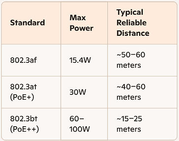
Distance by PoE Standard

Cable Type Matters
-
Cat5e: Common, but thinner wires may reduce usable distance for high power devices.
-
Cat6/Cat6a: Thicker conductors (23 AWG) help maintain voltage over longer runs.
-
Cat7: Offers shielding but no major PoE distance advantage over Cat6a.
PoE Cabling and Distances
Power over Ethernet (PoE) can power devices up to 100 meters (328 feet) over standard Ethernet cables this is the official limit set by IEEE standards like 802.3af, 802.3at (PoE+), and 802.3bt (PoE++). Real world performance depends on several factors, see the chart to the left.
Extending Beyond100 Meters
-
Use PoE extenders to boost signal and power.
-
Deploy media converters to switch to fiber optics.
-
Consider higher-voltage PSEs (up to 57V) for better long-distance performance.

Stand alone PoE Injector
PoE Injectors
What they do: Combine Power + Data: They “inject” DC power into the Ethernet line, allowing a single cable to carry both network traffic and electrical power. Injectors only provide power over ethernet when they properly sense P0E specific devices. They use a handshake process defined by IEEE PoE standards to detect whether the device on the other end is PoE‑capable before energizing the line with power + current requirements.
If the device is non‑PoE, the injector leaves the line unpowered, so regular Ethernet devices are safe. Make sure the PoE injector you use has the proper power rating to power your device properly. These devices can be located anywhere from the headend or midspan or at the endpoint, it can be located anywhere along that cable run.
Why Midspans Exist?
Not all switches provide PoE. A midspan solves that by:
-
Injecting 802.3af/at/bt power
-
Allowing you to keep your existing non‑PoE switch
Powering devices like:
-
IP cameras
-
Wireless access points
-
VoIP phones
-
Dante endpoints
-
AV‑over‑IP transmitters/receivers
Rack Mouted Managed PoE Switches
Common Certification Standards

Why Cable Certification Matters
Certified networking cables are Ethernet or fiber optic cables that have been tested and verified to meet specific industry standards for performance, safety, and reliability. These certifications ensure that the cables can handle the speeds, bandwidth, and environmental conditions required for modern networks.
-
Guarantees data integrity and consistent performance.
-
Ensures interoperability across devices and brands.
-
Reduces risk of network failures, signal loss, and EMI.
-
Meets building codes and legal compliance for commercial installs.
Types of Certified Cables
-
Cat5e/Cat6/Cat6A/Cat7/Cat8: Twisted-pair Ethernet cables certified for speed and shielding.
-
Outdoor-rated cables: Certified for UV, moisture, and temperature resistance.
-
Plenum/LSZH cables: Certified for low smoke and fire safety in air-handling spaces.
-
Fiber optic cables: Certified for signal loss, bend radius, and connector quality.
How to Identify Certified Cables
-
Look for markings on the cable jacket (e.g., UL, ETL, Cat6A).
-
Check for manufacturer documentation or test reports.
-
Use certification testers to verify installed cable performance.
Category Cable Types: Unshielded Twisted Pair (UTP), Shielded Twisted Pair (STP), Frequencies, Data Rate Specifications

Cable Distance Data:
-
Accurate up to 328 ft: Cat3, Cat5, Cat5e, Cat6 (1G), Cat6a, Cat7, Cat7a Not rated to 328 ft at full speed: Cat6 at 10G (55 m limit) and Cat8 at 25–40G (30 m limit)

UTP, STP Cable Jacket Types – Comparison Overview

RJ 45 Connector Types


Fiber-Optic Network Cable
Fiber optic cabling is the speed demon of the networking world, capable of transmitting data using pulses of light through strands of glass or plastic at long distances.
Why use Fiber Optic Cabling?
-
Extremely high speeds: 10 Gbps to 100+ Gbps
-
Longer range: Can span kilometers without significant signal loss or the need for signal repeaters
-
Immunity to: Electromagnetic and RF interference: Ideal for industrial, commercial and homes or any noisy AC-RF environments
-
Future-proof: Supports next-gen bandwidth demands
Types of Fiber Optic Cables

(OM) Stands for Optical Multimode
-
OM1/OM2: Older multi-mode, slower speeds
-
OM3/OM4/OM5: Laser-optimized, supports 10/40/100 Gbps
Define Your Network’s Purpose and Scope
Determine the following:
-
How many devices will be connected?
-
What kind of activities, AV, home automation, gaming, streaming, file sharing, and remote work.
-
Will it be wired, wireless, or hybrid.
This helps you choose the right gear and layout.
Create a Product Networking BOM (Bill of Materials)
-
Internet connection type and speed needed: Fiber or UTP copper cable or both.
-
Modem & router: Are they separate or combined? Do they support the speed you’re need and are paying for.
-
Select proper ethernet switches, number of ports needed, standard data only or data/Poe, managed/unmanaged, also type of wireless access setup and hardware.
-
How many cables & ports needed: RJ45 ports on devices, type of Ethernet cable (Cat5e, Cat6), wall jacks, adapters if needed.
Common Fiber Optic Connector Types


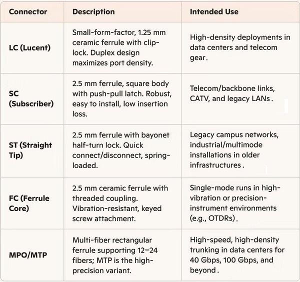
MPO (Multi-Fiber Push-On) and MTP (Multi-Fiber Termination Push-On) are types of multi-fiber connectors used in high-density fiber optic cabling systems, with MTP being a high-performance variant of MPO.
Duplex vs. Simplex

Duplex LC Fiber Optic Cable
-
Duplex connectors carry two fibers (one TX, one RX) for full-duplex links (common in Ethernet/Fibre Channel).
-
Simplex connectors use a single fiber for one-way transmissions, suitable for point-to-point sensor links or CWDM/DWDM taps.
Choosing the right connector depends on fiber type (single-mode vs. multimode), data rate requirements, density constraints, and environmental factors. Always verify compatibility with your transceivers, patch panels, and industry standards (e.g., TIA-568).


Cable Management & Cable Raceways
Cable management: Strategic organization, routing, and concealment of cables to:
-
Prevent tangling, damage, and signal interference
-
Maintain a clean and professional appearance
-
Support future upgrades and troubleshooting
-
Comply with safety and building codes
Cable Raceways: Enclosed channels that route and protect cables along walls, ceilings, or floors. They’re especially useful in retrofits or spaces where in-wall cabling isn’t feasible.
Benefits of Using Raceways:
-
Surface-mounted flexibility: Ideal for finished spaces
-
Modular components: Elbows, tees, end caps, and junctions for custom layouts
-
Aesthetic integration: Available in paintable finishes and low-profile designs
-
Code compliance: Keeps power and data separated per NEC standards
Cable Management Hardware for UTP and Fiber Cable:
1. Pathway Infrastructure
-
Cable Trays — ladder trays, basket trays, center‑rail trays
-
J‑Hooks — single, double‑mount, multi‑tier
-
Conduit — EMT, ENT, flexible conduit, innerduct for fiber
-
Raceways — surface‑mount, low‑voltage, divided raceways
-
Floor & Ceiling Pathways — raised floor channels, ceiling grid supports
2. Rack & Cabinet Cable Management
-
Vertical Cable Managers — finger‑duct, open‑channel, high‑capacity
-
Horizontal Cable Managers — 1U/2U, slotted, brush‑style
-
Lacing Bars — straight, offset, round, square
-
Cable Rings & D‑Rings — metal or plastic for routing bundles
-
Fiber Management Panels — sliding trays, patch enclosures, splice trays
3. Patch Panel & Termination Hardware
-
UTP Patch Panels — 24/48‑port, angled, flat, shielded
-
Fiber Patch Panels — LC/SC/MPO cassettes, adapter plates
-
Keystone Jacks & Modules — Cat5e–Cat8, shielded/unshielded
-
Termination Blocks — 110 blocks, 66 blocks (legacy), BIX/QBIX
-
Fiber Splice Hardware — splice trays, heat‑shrink sleeves, mechanical splices
4. Cable Securing & Support Hardware
-
Velcro Straps — reusable, wide‑band, low‑compression (preferred for fiber)
-
Cable Ties (Zip Ties) — nylon, stainless, releasable
-
Cable Tie Mounts — adhesive, screw‑down, rack‑mount
-
Cable Clamps — cushioned, metal, plastic
-
Grommets & Bushings — for rack entry points and pass‑throughs
5. Fiber‑Specific Protection Hardware
-
Fiber Raceway Systems — enclosed ducts, drop‑outs, elbows
-
Bend‑Radius Control Hardware — radius guides, spools, brackets
-
Fiber Slack Storage — slack wheels, storage trays, wall boxes
-
Connector Protection — dust caps, shuttered adapters
6. Wall, Ceiling, and Floor Hardware
-
Low‑Voltage Brackets — single/dual‑gang, old‑work, new‑construction
-
Wall Plates — keystone, fiber, brush plates
-
Floor Boxes — AV‑rated, low‑voltage compartments
-
Ceiling Boxes — plenum‑rated enclosures for APs and AV drops
7. Labeling & Identification Hardware
-
Cable Labels — wrap‑around, heat‑shrink, self‑laminating
-
Rack Labels — magnetic, adhesive, engraved
-
Patch Panel Labels — printed strips, modular inserts
-
Pathway Markers — conduit/raceway identification
8. Tools & Accessories
-
Cable Pulling Tools — fish tape, rods, pull socks
-
Cable Lubricant — for long conduit pulls
-
Punchdown Tools — 110/66
-
Fiber Tools — cleavers, strippers, inspection scopes
-
Cable Testers — UTP certifiers, fiber OTDRs
Wireless Technology
IEEE 802.11 Standards Evolution

Frequency Bands & Channels
-
2.4 GHz (UHF): Longer range, better wall penetration, more interference (Bluetooth, microwaves); 14 overlapping channels globally.
-
5 GHz (SHF): Higher capacity, shorter range; up to 25 non-overlapping channels in many regions.
-
6 GHz (SHF): Newly available for Wi-Fi 6E/7, provides cleaner spectrum and wider channels (up to 320 MHz) for ultra-low latency and multi-gigabit links.
Wi-Fi 8
-
Wi-Fi 8 officially designated IEEE 802.11bn. expected to be finalized in 2028, marking a significant evolution in wireless technology.
-
Wi-Fi 8, also known as IEEE 802.11bn, is set to introduce several major changes, focusing on Ultra High Reliability (UHR) rather than just speed. Key features include:
Dynamic Spectrum Management: Enhances spectrum efficiency by allowing devices to access multiple channels simultaneously, improving performance in crowded environments. -
Coordinated Multi-Access Point Features: Aims for seamless roaming and consistent performance across multiple access points, addressing challenges in low signal conditions.
-
Hardware-Accelerated Telemetry: Designed to support AI workloads at the network edge, ensuring reliable and efficient data transmission.
-
Focus on Reliability: Unlike previous generations that prioritized peak throughput, Wi-Fi 8 emphasizes stability and low latency, making it suitable for AI applications and high-density environments.
-
Wi-Fi 8 is expected to be finalized in 2028, marking a significant evolution in wireless technology.
Security Protocols
-
WEP: Original, now insecure and deprecated.
-
WPA: Interim fix using TKIP; better than WEP but vulnerable.
-
WPA2: AES-CCMP encryption; gold standard since mid-2000s.
-
WPA3: Introduced Simultaneous Authentication of Equals (SAE) and 192-bit security suite, protecting against offline dictionary attacks.
Robust security also demands unique SSIDs, strong passwords, regular firmware updates, and network segmentation for guest/IoT devices.
Outdoor Networking
Security Cameras and other outdoor technologies require specific enclosures, cabling and connectors/connectivity hardware to be used in harsh weather environments.
IP67 (Ingress Protection) Rating: What Does IP67 Mean? The IP67 rating indicates that a device is completely dust-tight and can withstand immersion in water up to 1 meter for 30 minutes.
The IP (Ingress Protection) rating system classifies the degree of protection provided by enclosures of electrical devices against solid objects and liquids. The IP67 rating specifically consists of two digits:
-
6: This first digit indicates that the device is dust-tight, meaning no dust can enter the enclosure, providing complete protection against dust particles.
Top Networking Product Manufactures

Ekahau Planning & Testing
What Is Ekahau?
Ekahau is the industry‑standard Wi‑Fi design, planning, and RF analysis platform used by network engineers, low‑voltage designers, and AV/IT integrators to create reliable wireless networks. It’s the tool professionals use to predict, measure, and optimize Wi‑Fi performance in commercial, enterprise, and large‑venue environments.
Software to use for Wi-Fi Surveys and Site Testing

Commercial Wif-Fi
Challenges of Large‑Scale Commercial Wi‑Fi Installations
1. Complex Building Materials & RF Attenuation
Large commercial environments introduce materials that dramatically affect RF propagation:
-
Concrete, steel, low‑E glass (low‑emissivity glass), The metallic Low‑E coating blocks RF energy. Low‑E glass uses a microscopically thin metal or metal‑oxide layer to reflect infrared heat. That same layer also reflects radio frequencies, including:
A.) 2.4 GHz Wi‑Fi
B.) 5 GHz Wi‑Fi
C.) 6 GHz Wi‑Fi (Wi‑Fi 6E/7)
D.) Cellular signals
E.) IoT RF bands (433 MHz, 915 MHz, etc.)
This makes Low‑E windows behave like partial Faraday cages.
-
Firewalls, elevator shafts, mechanical rooms
-
Dense shelving (warehouses, retail)
-
High‑ceiling atriums and open spaces
Each material changes signal behavior, requiring predictive modeling (Ekahau, iBwave) and careful AP (Access Point) placement.
2. High Client Density & Capacity Planning
Modern commercial spaces often support:
-
Hundreds or thousands of simultaneous devices
-
BYOD environments
-
IoT sensors, AV endpoints, automation systems
-
VoIP and real‑time traffic
Challenges include:
-
AP (Access Point) saturation
-
Channel congestion
-
Airtime fairness
-
Roaming performance
Capacity planning becomes just as important as coverage.
3. Channel Interference & Co‑Channel Contention
Large deployments must manage:
-
Overlapping channels
-
Neighboring tenant Wi‑Fi
-
Interference from AV gear, lighting control, security systems
-
Microwave, Bluetooth, Zigbee, and other 2.4 GHz noise sources
Poor channel planning leads to difficult Wi-Fi connectivity, dropped connections and slow throughput.
4. Multi‑Floor & Multi‑Building Coordination
Wi‑Fi signals bleed through floors and walls unpredictably. Challenges include:
-
Vertical channel reuse
-
AP power balancing
-
Stairwell and elevator shaft propagation
-
Outdoor‑to‑indoor interference
This is where predictive modeling and RF heatmaps become essential.
5. Power & Infrastructure Limitations
Large commercial deployments require:
-
Sufficient PoE/PoE+ budgets
-
Proper switch placement
-
Redundant pathways
-
Conduit and cable tray availability
-
IDF/MDF spacing
A poorly planned low‑voltage infrastructure can cripple even the best RF design.
6. Roaming & Handoff Performance
In large campuses, users move constantly:
-
Conference rooms
-
Hallways
-
Warehouses
-
Multi‑story offices
Challenges:
-
Sticky clients
-
Slow handoffs
-
Mismatched AP power levels
-
Inconsistent SSID configurations
7. Security & Segmentation
Enterprise Wi‑Fi must support:
-
Guest networks
-
Corporate networks
-
IoT/AV VLANs
-
Security cameras
-
Building automation
Challenges include:
-
Proper VLAN segmentation
-
Radius/802.1X authentication
-
Device onboarding
-
Rogue AP (Access points) detection
8. Installation Constraints & Trade Coordination
Common issues:
-
APs placed incorrectly by electricians
-
Ceiling obstructions (HVAC, lighting, sprinklers)
-
Aesthetic restrictions from architects
-
Last‑minute layout changes
This is why Wireless Coverage Plans and WAP Layout Sheets are critical in construction documents.
9. Ongoing Monitoring & Optimization
Large networks require:
-
Continuous RF monitoring
-
Firmware updates
-
Channel/power adjustments
-
Troubleshooting interference sources
-
Post‑installation validation surveys
Wi‑Fi is not “set it and forget it” — it’s a living system.
To Summarize
Large‑scale commercial Wi‑Fi installations fail when treated as simple AP placement. They succeed when treated as RF engineering projects involving predictive modeling, capacity planning, infrastructure design, and continuous optimization.
What is heat mapping
A Wi‑Fi heat map is a visual RF coverage map that shows how wireless signal behaves across a building or area. It uses color‑coded overlays on a floor plan to display signal strength, SNR, interference, channel overlap, and overall network health. This helps engineers identify dead zones, weak coverage, noise sources, and AP placement issues.
The Key benefit of a heat map is that it turns invisible RF performance into a visual, measurable, engineering‑grade diagnostic tool.
What a Wi‑Fi Heat Map Shows
Based on industry‑standard tools like Ekahau, Cambium Wi‑Fi Designer, NetSpot, and TamoGraph:
-
Signal Strength (dBm): Where coverage is strong vs. weak.
-
Signal‑to‑Noise Ratio (SNR): How clean the RF environment is.
-
Channel Overlap: How many APs interfere on the same channel.
-
Interference / Noise: RF congestion from other devices or networks.
-
Data Rates: Expected throughput at each location.
-
Capacity Health: Whether the network can support the number of clients.
These maps are generated either through predictive modeling (simulated AP placement) or active site surveys (walking the space with a measurement device like Ekahau Sidekick).
TamoSoft/TamoGraph Software:

The fastest, most precise Wi-Fi testing and measurement device now supercharged and tuned for 6 GHz, 5 GHz and 2.4 GHz. Ekahau Sidekick 2 Hardware/Software: Click Here

Why Heat Mapping Is Important in Wireless Network Design
Heat mapping is essential because it: Heat mapping plays a critical role in designing and validating Wi‑Fi networks because it provides a visual, data‑driven view of how wireless signals behave in a real environment. It helps engineers:
-
Eliminate guesswork by showing exactly where access points should be placed for optimal coverage
-
Reveal weak spots or dead zones that need additional APs or configuration changes
-
Show the impact of walls, materials, and physical obstructions on RF performance
-
Improve channel planning by identifying areas of interference or channel overlap
-
Confirm that the network meets performance and reliability requirements before deployment
-
Verify actual performance after installation, ensuring the system operates as designed
-
Advanced platforms such as Ekahau and Cambium Wi‑Fi Designer also offer 3D heat mapping, allowing designers to evaluate vertical coverage, antenna patterns, and downtilt effects for more accurate enterprise‑grade wireless planning.
How Wi‑Fi Heat Maps Are Created
Creating a Wi‑Fi heat map typically follows a consistent process across professional wireless design tools. The workflow usually includes:
-
Loading or drawing the floor plan for the building or area being analyzed
-
Setting the scale so the software can calculate accurate distances
-
Placing access points for predictive modeling or walking the site with a survey device to capture real RF data
-
Collecting wireless measurements, including signal strength, noise levels, and interference
-
Generating visual heat maps that display coverage, SNR, channel overlap, and other performance metrics
Platforms such as NetSpot and TamoGraph produce interactive, color‑coded visualizations that clearly show strong coverage zones, weak areas, and interference patterns, making it easier to evaluate and optimize the wireless design.
Why Professional, State‑of‑the‑Art AV/IT Hardware, Wiring, and Designs Are Critical in Commercial Installations
1. Reliability Under Heavy, Continuous Use
Commercial environments demand equipment that runs:
-
All day
-
Every day
-
Under high load
-
With minimal downtime
Professional‑grade manufacturers design hardware for:
-
Thermal stability
-
Long duty cycles
-
High connection counts
-
Continuous PoE loads
-
Enterprise‑level RF performance
Consumer‑grade or budget hardware simply cannot sustain this.
2. Predictable Performance & Standards Compliance
Commercial systems must meet strict performance and safety standards:
-
IEEE networking standards
-
UL/ETL low‑voltage safety
-
NEC code compliance
-
EIA (Electronic Industries Alliance) and TIA (Telecommunications Industry Association)
cabling standards
Using certified hardware, cabling, and connectors ensures:
-
Proper bandwidth
-
Correct PoE delivery
-
Stable RF propagation
-
Accurate signal integrity
This is essential for Wi‑Fi, AV‑over‑IP, VoIP, security, and automation systems.
3. Proper Infrastructure for Future Scalability
Professional‑grade wiring and components support:
-
Higher data rates (Cat6A, fiber)
-
Increased PoE budgets
-
Additional APs (Access Points), cameras, AV endpoints
-
Future upgrades without re‑cabling
Cheap cabling or connectors become the bottleneck — and the most expensive part of a system to replace later.
4. Interoperability Across Systems & Vendors
Commercial buildings integrate:
-
Wi‑Fi
-
AV distribution
-
Security
-
Access control
-
Building automation
-
Lighting control
-
Video conferencing
Professional manufacturers follow strict interoperability standards, ensuring:
-
Stable network behavior
-
Predictable device discovery
-
Reliable AV‑over‑IP transport
-
Clean handoffs between systems
This reduces troubleshooting and avoids finger‑pointing between trades.
5. Reduced Failure Points & Lower Long‑Term Costs
Professional hardware and connectors:
-
Fail less often
-
Maintains signal integrity
-
Resist corrosion and mechanical stress
-
Provide consistent PoE delivery
-
Reduce packet loss and RF noise
This lowers:
-
Service calls
-
Downtime
-
Replacement costs
-
Warranty claims
Cheap parts cost more in labor and rework than they save upfront.
6. Better Installation Quality & Trade Coordination
Commercial‑grade designs ensure:
-
Correct AP placement
-
Proper rack layouts
-
Cable management and labeling
-
Conduit and pathway planning
-
Heat load and power distribution
This prevents:
-
Overheating
-
Signal interference
-
Poor Wi‑Fi coverage
-
AV dropouts
-
Network bottlenecks
Professional design = predictable installation.
7. Security, Compliance & Risk Reduction
Enterprise‑grade hardware includes:
-
Secure firmware
-
WPA3‑Enterprise
-
802.1X authentication
-
VLAN segmentation
-
Logging and monitoring
Cheap hardware introduces:
-
Vulnerabilities
-
Firmware exploits
-
Rogue AP risks
-
Compliance failures
Commercial clients cannot afford that exposure.
8. Professional Designs Enable Accurate Documentation
High‑quality systems require:
-
CAD drawings
-
Wireless coverage plans
-
Rack elevations
-
Network topology diagrams
-
Cable schedules
-
As‑builts
Professional hardware and wiring ensure the documentation matches real‑world performance.
To Summarize
Using professional‑grade manufacturers, wiring, connectors, and engineered designs is not a luxury, it’s the foundation of a reliable, scalable, secure commercial system. It ensures the installation performs as intended, supports future growth, and minimizes long‑term cost and risk.
Wi-Fi for Outdoor Home & Commercial Installations
Concerns for Installing Outdoor Wi‑Fi Access Points (General + Coastal Environments)
1. Weather Exposure
Outdoor APs face constant environmental stress:
-
Rain, snow, and humidity infiltration
-
UV degradation of plastics and seals
-
Temperature swings affecting electronics
-
Wind‑driven debris impacting enclosures
Requirement: Use APs with proper outdoor ratings (IP65/IP67), UV‑stable housings, and weather‑sealed cable glands.
2. Salt Air and Corrosion (Critical for Coastal Installations)
Ocean environments dramatically accelerate corrosion:
-
Salt deposits attack metal connectors, antennas, and mounting hardware
-
Corrosion can penetrate PCB components if seals fail
-
Rusted fasteners weaken mounting points
-
Salt fog reduces lifespan of exposed antennas
Requirement:
-
Marine‑grade stainless steel hardware
-
Corrosion‑resistant coatings
-
Regular cleaning and maintenance
-
Avoiding exposed copper or untreated metal surfaces
3. Moisture Intrusion & Condensation
Even sealed APs can experience:
-
Internal condensation from temperature swings
-
Water ingress through poorly sealed cable entry points
-
Moisture wicking through improperly rated cables
Requirement:
-
Use outdoor‑rated Ethernet (gel‑filled or direct‑burial)
-
Drip loops on all cables
-
Weatherproof junction boxes where needed
4. Power and Grounding Challenges
Outdoor APs require stable power and proper grounding:
-
Lightning strikes and surges are more common outdoors
-
Improper grounding can damage APs or switches
-
Long cable runs increase voltage drop
Requirement:
-
Use surge protectors on both ends of the Ethernet run
-
Proper bonding to building ground
-
PoE budget planning for long distances
5. Mounting and Structural Stability
Outdoor mounting introduces mechanical risks:
-
High winds can loosen or damage mounts
-
Vibration can affect antenna alignment
-
Poor placement can cause shading or signal blockage
Requirement:
-
Secure, rated mounting hardware
-
Avoid mounting under metal awnings or
behind structural beams
-
Maintain clear line‑of‑sight for directional antennas
6. RF Performance Issues Outdoors
Outdoor RF behaves differently:
-
Reflections from water surfaces
-
Signal absorption from foliage
-
Interference from neighboring properties
-
Large open spaces requiring higher‑gain antennas
Requirement:
-
Proper antenna selection (sector, omni, directional)
-
Outdoor‑specific channel planning
-
Heat mapping and predictive modeling
7. Wildlife and Physical Damage
Outdoor APs are exposed to:
-
Birds nesting on or near APs
-
Rodents chewing cables
-
Insects entering vents or housings
Requirement:
-
Use screened vents
-
Rodent‑resistant cabling
-
Bird‑deterrent mounting strategies
8. Security and Vandalism
Outdoor APs are more vulnerable to:
-
Theft or tampering
-
Physical damage
-
Unauthorized access to exposed cabling
Requirement:
-
Tamper‑resistant enclosures
-
Secure mounting height
-
Lockable junction boxes
9. Maintenance and Accessibility
Outdoor APs require more frequent inspection:
-
Cleaning salt buildup
-
Checking seals and gaskets
-
Verifying mounting integrity
-
Firmware and performance monitoring
Requirement:
-
Plan for accessible mounting locations
-
Schedule periodic maintenance cycles

Inline RJ45 Outdoor Ethernet POE+ / RJ-45
Surge Protector (Shielded) for
Thunder & Lightning Protection
(up to 1 Gigabyte)
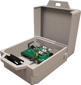
Ethernet Surge Protector Outdoor for PoE+ Gigabit 1000Mbs - LAN Network Thunder Lightning Surge Protection Suppressor/Arrester.
Mounting holes to mount to the wall, electric Panel or network rack cabinet - box Lock option.
MDF vs. IDF Network Closets Main Distribution Frame (MDF), Intermediate Distribution Frame (IDF)

Main Distribution Frame (MDF)
The MDF is the primary network and telecommunications room for a building. It serves as the central hub where all external services enter, including ISP circuits, fiber demarcation points, and core routing infrastructure. The MDF typically houses core switches, firewalls, servers, PBX/VoIP systems, and security head‑end equipment such as NVRs and VMS servers. All IDF closets connect back to the MDF through high‑bandwidth fiber uplinks, making it the backbone of the building’s network architecture.
Intermediate Distribution Frame (IDF)
Intermediate Distribution Frame (IDF) IDF closets extend the MDF’s network to each floor or zone of a building. They contain access‑layer switches, PoE distribution for CCTV cameras, wireless access points, access control devices, and horizontal cabling terminations. IDFs are strategically placed to maintain proper cable lengths, reduce latency, and ensure reliable connectivity for all edge devices. Each IDF connects upstream to the MDF via fiber, enabling high‑performance transport of video, data, and control traffic.How They Work Together The MDF acts as the central command point, while IDFs distribute connectivity outward to users, cameras, and building systems. In security deployments, CCTV cameras typically home‑run to the nearest IDF for PoE and switching, while recording NVR servers and management platforms reside in the MDF. This architecture ensures scalable bandwidth, clean cable management, and reliable system performance across the entire facility.
42U Server Rack
with Locking Security Doors and Side Panels

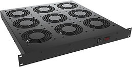
Rack Mount Fan Tray
Fan trays can be positioned at the bottom of a rack to force air through the cabinet, at the top to exhaust air out or below specific pieces of equipment for spot cooling.

Solid Blank Rack Mount Panels
Black 19" Metal 1U, 2U, 4U
Vented Rack Panel
Black 19" Metal 1U

Remote IT Access Management Software
Remote computer and server access software allows IT teams to securely connect into systems from anywhere, enabling fast troubleshooting, updates, and support without needing to be physically on‑site. Some companies have their own software to access their Hardware and Systems and other companies use 3rd party software remote assistance or Tech Support.
Third‑Party Remote Access Software in IT Support
Third‑party remote access platforms allow IT teams, technicians to securely connect to computers, servers, and networked devices from any location. These tools provide encrypted sessions, multi‑factor authentication, session logging, file transfer, remote command execution, and full desktop control, making them essential for troubleshooting, patching, system administration, and end‑user support. In enterprise environments, remote access software reduces downtime, accelerates incident response, and eliminates the need for on‑site technicians. Many platforms also integrate with ticketing systems, identity management, and compliance frameworks to support secure, auditable IT operations.
Leading Companies Offering Remote Access Software
Below is a list of the most widely used third‑party remote access providers in IT, MSP, and enterprise environments:
Enterprise‑Grade Remote Access Platforms
-
TeamViewer: Full remote control, cross‑platform support, IoT and industrial integrations
-
AnyDesk: Lightweight, low‑latency remote desktop with strong encryption
-
LogMeIn / GoTo Resolve: Enterprise remote support, monitoring, and management
-
ConnectWise ScreenConnect: MSP‑focused remote support and unattended access
-
RemotetoPC: Remote access computer program for home, business and IT
-
Splashtop: High‑performance remote desktop with strong security and compliance options
-
BeyondTrust Remote Support: Privileged access management and secure remote sessions
-
Dameware (SolarWinds): On‑prem and cloud remote control for Windows environments
Cloud & Hybrid IT Management Platforms with Remote Access
-
NinjaOne: RMM platform with built‑in remote access and automation
-
Atera: MSP platform with integrated remote monitoring and remote desktop
-
Kaseya: VSA – RMM with remote control, patching, and automation
-
ManageEngine Remote Access Plus: Enterprise remote troubleshooting and device management
Open‑Source / Self‑Hosted Options
-
RustDesk: Open‑source alternative to TeamViewer/AnyDesk
-
Apache Guacamole: Browser‑based remote desktop gateway (RDP, VNC, SSH)
-
MeshCentral: Self‑hosted remote management and remote desktop
Remote Access Built Into OS Platforms
-
Microsoft Remote Desktop (RDP): Native Windows remote access
-
Apple Remote Management / Screen Sharing: macOS remote control
-
SSH (OpenSSH): Secure remote command‑line access for Linux/Unix systems